 跳到内容
跳到内容 

A VFD is a power control device that uses frequency conversion technology and microelectronics technology to control AC motors by changing the frequency of the motor’s power supply. The frequency converter adjusts the output power supply’s voltage and frequency by turning on and off the internal IGBT, providing the motor with the required power voltage according to its actual needs, thereby achieving the purpose of energy saving and speed regulation.
Many frequency converters are used in similar ways. As a professional frequency converter manufacturer, KUVO, we will introduce 3 common and simple methods to control frequency converters below.
1.Panel Control
Control of the frequency converter can be achieved through the panel of the frequency converter, including starting and stopping the frequency converter, modifying the frequency, and other functions.
Taking KUVO’s JHI780 as an example. Below is the control panel of the JHI780.
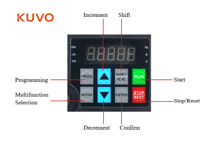
PROG: Programming, Enter or exit Level I menu.
M-FUN: Multifuction, Function switch selection. It can be defined as a command source, or as a fast direction switch, according to P7-01.
Increment button: Increase data or function code.
Decrement button: Decrease data or function code.
SHIFT button: Select the displayed parameters in turn in the stop or running state, and select the digit to be modified when modifying parameters.
ENTER: Enter the menu interfaces level by level, and confirm the parameter setting.
RUN: Start the AC drive in the operation panel control mode.
STOP: Stop the AC drive when it is in the running state and perform the reset operation when it is in the fault state. The functions of this key are restricted in P7- 02.
2. External Control
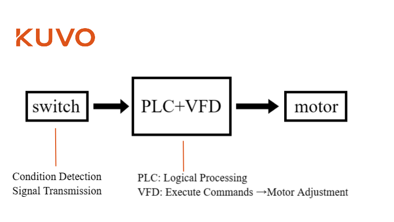
It can also be controlled through an external controller or a contactor. This control method mainly involves the controller, such as a PLC, sending start/stop signals and frequency signals to the VFD.
a. External Switches
External switches can be any form of physical switch or sensor, used to detect specific conditions (such as temperature, pressure, position, etc.) or for manual input of control commands. When these conditions are met or the switch is activated, they send an electrical signal to the PLC.
Taking KUVO’s JHI780 as an example.
To connect an external switch to the device, you would typically use the digital input (DI) terminals provided on the device.
Digital Input (DI) Terminals
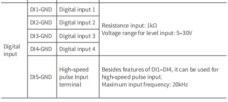
DI1-GND, DI2-GND, DI3-GND, DI4-GND, DI5-GND:
These terminals are used for connecting digital inputs, including external switches. Each DI terminal has a specific function, and you can configure these functions according to your requirements. The DI terminals support a voltage range for level input of 5–30V, and they have a resistance input of 1kΩ.
Connecting an External Switch
- Identify the DI Terminal: Determine which digital input terminal (DI1, DI2, DI3, DI4, or DI5) you will use for the external switch. This choice may depend on the specific function you want to assign to the switch.
- Prepare the Switch and Wiring: Ensure that your external switch is compatible with the voltage levels supported by the DI terminals (5–30V). Prepare appropriate wiring to connect the switch to the chosen DI terminal and the ground (GND).
- Connect the Switch: Connect one wire from the external switch to the chosen DI terminal on the device. Connect the other wire from the switch to the ground (GND) terminal.
- Configure the Function: Depending on the device’s capabilities, you may need to configure the function of the DI terminal to recognize the external switch. This configuration can typically be done through the device’s settings or programming interface. Look for parameters related to digital input functions and assign the desired action to the switch.
- Test the Connection: After connecting the switch and configuring the settings, test the switch to ensure it performs the desired action. This may involve monitoring the device’s response or using diagnostic tools to verify the input signal.
b. How to connect contactor
Typically, a contactor is used in electrical engineering to control the flow of electricity to components or systems, acting as a relay for high-power circuits. Connecting a contactor usually involves:
- Identifying the Contact Points: Contactors have several contact points, including power inputs (usually labeled L1, L2, L3 for three-phase systems) and outputs (T1, T2, T3), along with a coil (A1, A2) that operates the contactor.
- Wiring the Power Circuit: Connect the power supply lines to the input contacts of the contactor and the output lines that lead to the device or load to the contactor’s output contacts.
- Wiring the Control Circuit: The coil of the contactor is energized to close the contacts and allow current to flow through the power circuit. The control circuit typically involves a lower voltage and may include switches, relays, or other control devices connected to the coil terminals.
- Ensuring Safety and Compliance: Always ensure that the contactor is correctly rated for the voltage and current of the circuit it controls. Follow all safety guidelines and local electrical codes during installation.
3.Communication Control
Communication control allows devices to interact through data exchange, enabling efficient operation of automated control and monitoring systems. The most common communication protocol used is Modbus.
How to Connect:
- Connection: Use an RS485 communication cable to connect the frequency converter to the corresponding interface of the control system.
- Configure Communication Parameters: This includes setting the baud rate, data bits and stop bits, parity, and slave address.
- Write Control Logic as Needed: Use function codes defined by the Modbus protocol to read from or write to the frequency converter’s registers. Access parameters and send control commands through registers, such as setting the operating frequency, start and stop commands, etc.
- Implement Control.
- Monitor and Debug.
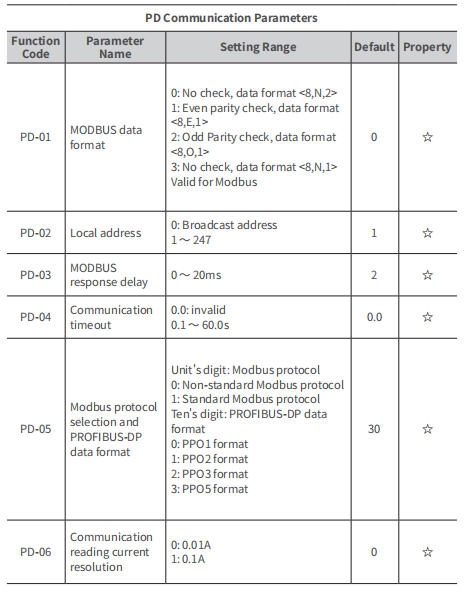
Below are the key debugging parameters for the JHI780.
- PD-01: Modbus data format (options include no check, even parity check, odd parity check, with different data formats like <8,N,2>, <8,E,1>, <8,O,1>, <8,N,1>)
- PD-02: Local address (range from 1 to 247, with 0 being the broadcast address)
- PD-03: Modbus response delay (0 to 20ms)
- PD-04: Communication timeout (0.1 to 60.0s)
- PD-05: Modbus protocol selection and PROFIBUS-DP data format
- PD-06: Communication reading current resolution
Controlling VFDs efficiently requires understanding the various methods available and selecting the one that best suits your application’s needs. Whether through manual control, external devices, or advanced communication protocols, mastering these control methods can significantly enhance the performance and functionality of your VFD-operated systems. If you still have any questions,please do not hensitate to contact us. We, KUVO VFD manufacturer, will always willing to help you!
